Automated Inspection Software for "True" Product Quality
There are two critical pieces to any automated visual inspection solution: a camera or imaging system to capture images of a device under test (DUT), and a software application that can process and analyze those images to identify and characterize any defects. For the hardware component, Radiant’s ProMetric® Imaging Photometers and Colorimeters have long provided high-resolution, low-noise image capture for lighting and display device makers.
This week we’ll take a look at the other key element: the applications used to analyze images. Radiant’s growing family of TrueTest™ Software modules offer customized solutions to meet the quality inspection needs of manufacturers in consumer electronics, lighting, and (insert your industry here). For virtually every inspection application, Radiant offers a software solution.
Automating Visual Inspection
The field of automated visual inspection (AVI)—also referred to as automated optical inspection (AOI)—has enabled manufacturers of a vast range of products to increase efficiency and quality. Applying AVI/AOI in the production process increases efficiency and lowers per-unit inspection costs, meaning that consumers benefit from the availability of high-quality, defect-free products at a reasonable price.
When testing the quality of illuminated components and displays, or looking for defects in assemblies and surfaces, manufacturers may need to perform multiple tests to inspect products across a range of evaluation criteria. With TrueTest, these multiple tests can be set up to run in sequence using a single image captured by a ProMetric system, enabling manufacturers to perform automated inspection at production-line speeds.
For customers who want to further customize an inspection solution, TrueTest’s robust API (application programming interface) and SDK (software development kit) are available.
Specialized Modules for Specialized Applications
Over the last few years, Radiant has developed and released a series of new modules as add-ons to the core TrueTest Software. Each of these software modules offers application-focused sets of capabilities. The “TT” modules package together analyses that are relevant for unique customer segments and devices—for example, TT-ARVR™ is a version of standard TrueTest with specific tools for addressing inspection of displays in augmented and virtual reality (AR/VR) devices. These TrueTest modules are described below.
TT-ARVR™ Helps Perfect the View Through Augmented- Virtual- and Mixed-Reality Headsets
AR/VR is a booming industry, with applications that include gaming, medicine, education, industrial operations, military, and more. Manufacturers of VR headsets, AR smart glasses and other near-eye displays (NEDs) can use TT-ARVR in conjunction with Radiant’s AR/VR Lens to measure the performance of their devices.
Because these devices are worn close to the eye, even tiny defects can appear magnified in the viewer’s perception. TT-ARVR includes tests to evaluate light and color (photometric) properties and identify defects in NED displays across a wide field-of-view that matches a user’s visual field.
For example, contrast is an important performance parameter for augmented- and mixed-reality devices, where the user’s ambient environment is visible behind text and symbols projected onto the display’s transparent surface. Having sufficient contrast ensures that images will be easily readable in all real-world environments and lighting conditions.
TT-ARVR includes a variety of tests to measure aspects of visual contrast and clarity, including MTF (modulation transfer function) Slant Edge, MTF Line Pair, and a unique MTF LSF (Line Spread Function) test developed at Radiant that corrects some of the errors that can arise when traditional MTF analysis is applied to AR/MR displays. Learn more about TT-ARVR by watching this product demo.
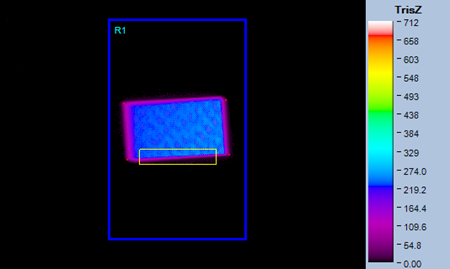
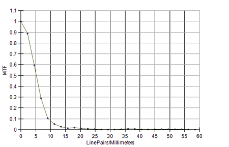
MTF is calculated to determine overall image clarity. The above example uses MTF Slant Edge analysis, shown in false color scale (top) and graphically (bottom).
TT-HUD™ Ensures Accurate Head-Up Display Projections in Automobiles and Aircraft
Head-up displays (HUDs) are becoming more and more common in automobiles; they’ve been a part of airplane cockpits for decades. A HUD allows information to be projected onto the windshield or a small screen in front of a driver’s line of sight, so the driver doesn’t have to look down and take their eyes off the road to see instruments, operating data (such as speed), and navigational information.
HUDs pose unique measurement challenges for manufacturers. As with AR/MR systems, HUD images are viewed on a transparent screen with the ambient environment still visible behind them. TT-HUD allows automotive and aerospace display makers to measure luminance, contrast, and clarity to ensure the accuracy and visibility of HUD virtual images and projections day or night, under any viewing conditions.
For example, HUDs can be subject to a defect called “ghosting” where a secondary ghost image appears to duplicate the primary image, obscuring the clarity and readability of the information and posing a potential hazard for drivers or pilots. TT-HUD includes a special Ghosting Analysis function to help manufacturers identify and correct this defect, whether ghost images appear overlaid or separate from the primary image. Learn more about TT-HUD.
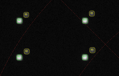
TT-HUD detects duplicate projections (overlapping or separated from the primary image) that are caused by ghosting effects using the Ghosting Analysis function.
TT-AutomotiveDisplay™ Helps Get In-Vehicle Displays Road-Ready
Automotive displays in the vehicle cockpit are not only viewed under variable lighting conditions, but they are also subject to temperature, vibrations, arbitrary viewing angles, and other factors. Today’s cars include multiple display screens integrated at a variety of fixed positions relative to passengers and drivers, so there is little control over how the environment might affect display visibility.
TT-AutomotiveDisplay helps automakers ensure the visual quality of in-vehicle displays of various shapes, sizes, and treatments, including those with anti-glare or anti-reflective coatings. TT-AutomotiveDisplay measures light, color, and mura (blemishes) with specific tests relevant to automotive industry quality requirements, such as ANSI brightness and DFF (German Flat Panel Display Forum) black mura standards.
One problem common to many automotive displays is called “sparkle”—the grainy effect caused by the application of anti-glare films and layers. While these layers help reduce the glare caused by sunlight and other ambient light sources shining onto a vehicle display, they can also cause visual interference if not carefully selected for the characteristics of a specific display. TT-Automotive Display contains a Sparkle analysis function that measures this visible variation as it is perceived by human observers, allowing automakers to correct display quality. Learn more about TT-Automotive Display.
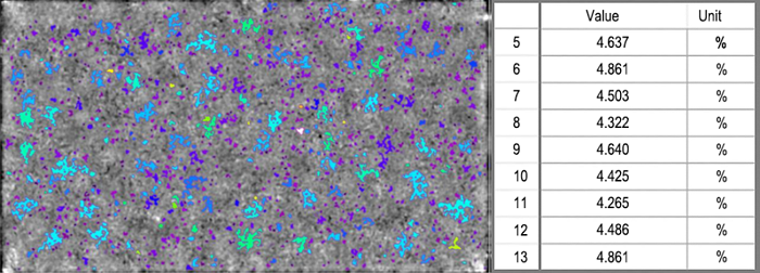
TT-AutomotiveDisplay Software outputs a value for the visible effect of sparkle (pixel-level luminance variation) for each region of a display, then calculates an average value across the display. This value can be used to pass or fail displays based on an established tolerance.
TT-NIRI™ Evaluates Invisible Near-Infrared Light Emissions
Near-infrared (NIR) wavelengths (which range from approximately 700-1500 nanometers) are invisible to the human eye, but they have many applications. NIR LEDs and lasers are being used today in facial and gesture recognition systems, in automotive LiDAR for autonomous vehicle sensing, for eye tracking and iris scanning, and for a variety of other detection, proximity, and 3D sensing tasks.
When used together with Radiant’s Near-Infrared (NIR) Intensity Lens, the TT-NIRI software module helps users measure and analyze near-infrared light wavelengths.TT-NIRI incorporates tests to evaluate the accuracy of 850 or 940 nm LEDs and lasers, and unique emission geometries like structured dot patterns and “flood” sources.
Measuring Structured Light Patterns. To produce a structured light pattern, a single NIR laser emission is projected through an optical component called a diffractive optical element, or DOE. A DOE splits the laser into multiple emission points, which cast an array of tiny invisible dots in a grid onto a 3D object, such as a person’s face.
When the light from each dot is reflected back from the object surface and received by the NIR sensor, the device calculates deformations in the pattern to determine the contours of the object. Effectively, the NIR structured light grid creates a “map” of an object’s 3D features. Structured light sensing is a common method used in biometric security such as facial recognition devices for smart phones and other protected devices or media. Learn more about measuring NIR light sources with TT-NIRI.
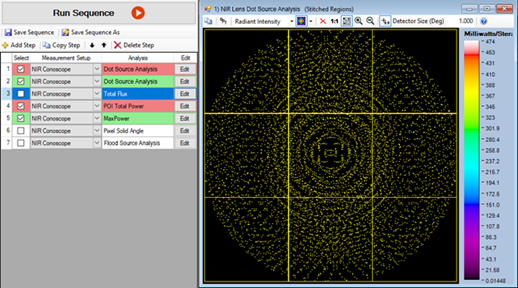
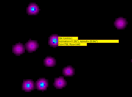
The TT-NIRI software module automatically identifies and counts each dot in a structured light pattern (top) as a point of interest and outputs data on each dot (bottom) such as inclination, azimuth, and radiant intensity (W/sr).
Whatever the visual inspection and measurement challenge, Radiant’s software engineers are working on new solutions each day to help meet the next challenge head on. Explore Radiant’s application software, already helping manufacturers around the globe ensure product quality and market viability.
Join Mailing List
Stay up to date on our latest products, blog content, and events.
Join our Mailing List
