Liquid Lenses Enable AR/VR Devices to Match Human Visual Dynamics
Liquid lenses were first developed by French scientist Bruno Berge1 in the mid-1990s based on the concept that manipulating the shape of a liquid changes how it refracts light, the same way glass lenses with different shapes exhibit different light refracting properties. Berge founded a company in 2002 called Varioptic to commercialize the technology, which was acquired by Corning in 2017 and now sold unde the Varioptic® brand name.
With traditional lenses (both fixed focal length and zoom) components are solid. Changing lens properties, such as changing the focal distance, can only be done by physically moving the location of the lens manually or mechanically. For example, adjusting the focus of a microscope requires twisting a knob to adjust the height of the lens (distance from the sample).
A camera zoom lens might be able to adjust focus automatically with a combination of sensors and user input, using battery power to change the position of lens components. But with these methods, there is a delay while components are physically adjusted. With liquid lenses, however, changes take just milliseconds.
Electrically Tunable Lenses
A common method for creating liquid lenses today, called “electrowetting,” requires two non-mixable liquids (such as oil and water). The curved interface where the two liquids meet becomes the optical element—it acts as the lens. Applying electrical current changes the curvature of the “lens” by changing the radius of the optical element (increasing electrostatic pressure).
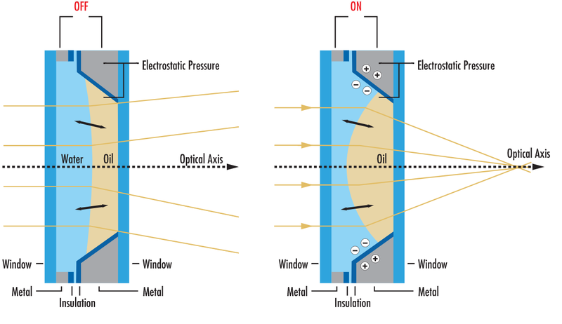
Diagram illustrating the working principle of an electrowetting liquid lens, in this case the Corning® Varioptic® variable-focus liquid lens. (Image © Corning)
The higher the voltage applied, the greater the resulting curvature, which changes the focal length of the lens. Liquid lenses—also referred to as electrically tunable or “smart” lenses—can even switch from convex to concave. This rapid adjustment makes liquid lenses useful for multiple applications. “Having the ability to focus both closely and to optical infinity in milliseconds makes integrating liquid lenses an ideal choice for applications that require focus at multiple distances where objects under inspection are different sizes or are at different distances away from the lens.”2
Millisecond adjustment time is just one of the advantaged that liquid lenses offer over traditional glass or plastic. Because they don’t require mechanics for operation, they facilitate compact system designs. They can even be used to replace individual lens layers within a full lens assembly to reduce overall size and weight.
They also provide a wide range of focal lengths, replacing many fixed-focal-length lenses and bulkier zoom lenses. Additionally, liquid lenses can be up to 85% smaller3 than standard camera lenses, making them suitable for use in mobile and optical device applications that need to minimize size and weight.

Different shapes of a 6mm liquid lens at different voltages, from convex to flat to concave. (Image source: Phillips/Phys.org)
Liquid lenses also consume very little power. Compared to typical optical devices that need to make mechanical adjustment to change focus or magnify the image being captured, liquid lenses require just a fraction of the power to adjust. And, ith no moving parts to wear out, liquid lenses are also more durable: “typical mechanical lenses are capable of ~100,000 cycles, whereas a liquid lens can withstand approximately ~50,000,000 cycles.”4
There are some challenges involved with using liquid-based tunable lenses, however. They offer only a small aperture size, at most 16 mm diameter. Because of this, they have limited sensor coverage and can only be used with sensors up to 1/1.8” (if the lens is retrofitted onto the front of an existing lens).5
Additionally, liquid lenses can be difficult to integrate with some types of equipment. They do work well in conjunction with filters and apertures, such as those required for high-speed applications that use distance sensors or controllers. They are relatively versatile, for example they can be implemented in various locations of an imaging system, embedded within or threaded to an imaging lens. When embedded inside of a system, the sensor coverage is not limited.6
Applications for Liquid Lenses
With their small size, high-speed adjustment, versatility, and low power consumption, liquid lenses have rapidly found a place in systems and devices used for a wide range of applications, for example:
- Smart phone cameras – the compact size and power efficiency of liquid lenses are ideal for mobile devices.
- Machine vision – for applications requiring rapid automated inspection such as barcode reading, package sorting, and quality control
- Drones and unmanned aerial vehicles – the rapid variable focus of a liquid lens can adjust dynamically as an airborne unit travels at different heights above the ground or distances from objects. They’re particularly useful in applications such as agricultural inspection and monitoring, geographic information/mapping systems, and surveillance.
- Measurement and dimensional rendering – “When paired with a distance sensor and camera, a liquid lens can quickly image different planes of a 3D object. The images are then stitched together in software to create an accurate three-dimensional rendering.”7
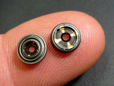
Tiny liquid lenses. (Image Source)
Another application where these small, variable-focus lenses are especially useful is in AR/VR devices that “need compact, light-weight, fast and low power consuming, as well as silent, lenses for zooming and focusing.”8
Liquid Lenses in AR/VR/MR
It’s becoming more common that AR/VR/MR (collectively XR) headsets are designed with multiple focal distances for more natural viewing scenarios. Multi-focal, varifocal, and foveated optics create a more natural viewing experience matched to the operation of the human visual system. Our eyes have a foveal region (an area of clear focus in the center of where the eye is pointed), and peripheral perception (images around the fovea are progressively less focused). For example, XR device optics might have focal point for perceiving elements as “near”, and a second focal point for elements far away.
With a liquid lens, it’s possible to sweep over a range of focus distances, which more closely matches human vision than a device with only two or three focal planes. Liquid lenses promise to provide split-second, high-resolution tunable focus adjustments to keep up with the speed of the human visual system.
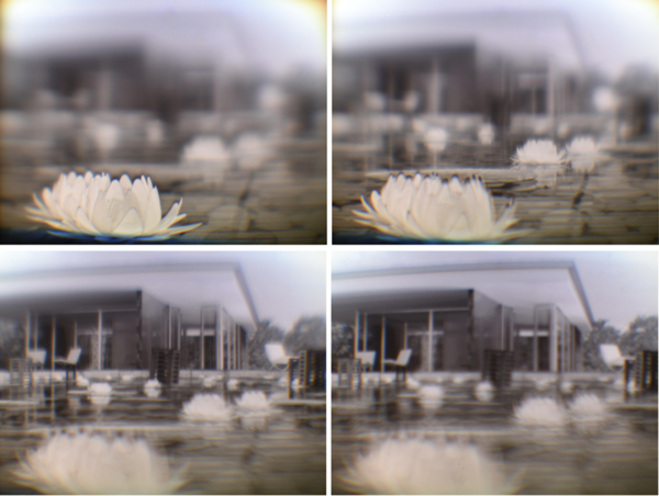
Example of images using a liquid lens to produce ‘sweeping’, where multiple focal distances can be emulated with a single optical component in the headset, to focus on the flower or the foreground (top) and gradually shift focus back to the building and the background (bottom). (Image Source)
Measuring Variable-Focus XR Devices
Methods to accommodate shifting focal distances in XR devices, including liquid lenses, are helping to create a more realistic and optically comfortable experience for device users. But they present a unique challenge for testing display quality. ARVR systems with fixed optics need to be measured to ensure sufficient image sharpness, brightness, contrast, color, and other characteristics. With a varifocal system, these measurement parameters must now be measured at each different intended focal distance or region.
However, imaging metrology systems used for display testing have traditionally relied on lenses with manual focus, which are problematic for several reasons. Any manual adjustment of the measurement system can introduce error, so of course this is an issue with manual lenses. Without computational checks and balances, manual focus may also unintentionally shift during measurement.
If this happens, poor focus could impact the accuracy of the results. For instance, the sharpness of a virtual image in an XR headset is often tested by calculating an MTF measurement. If poor focus of the measurement system introduces low image clarity, the XR display could fail the MTF test. Consider the images below. As the display falls out of focus, the yellow edge of the shape captured in the headset becomes blurry. In a slant-edge MTF analysis like this, the display would fail, by no fault of the display—simply because poor focus was introduced by the measurement optics.
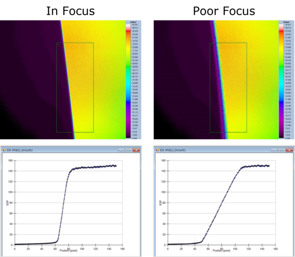
The impact of poor measurement focus on an MTF slant-edge analysis. An accurate measurement can be captured with the display in focus (left). But as the display falls out of focus (right), the yellow edge of the shape captured in the headset becomes blurry, causing an inaccurate MTF measurement.
When extension-focus lenses are used, a measurement system’s aperture actually moves with each focus change. This is critical in XR display testing because the position of the measurement system’s aperture is meant to emulate the position of the user’s pupil to characterize exactly what the user would see in the headset.
In these cases, the measurement system would need to be repositioned whenever the focus of the device is adjusted to reset the aperture to the correct location, which not only takes time but increases the risk that there could be an error in measurement setup. Manually adjusting the measurement set up for every slight change in focus is inefficient, inconvenient, and completely impractical for mass-production testing.
Another drawback of manual-focus lenses is that they make it nearly impossible to perform an effective through-focus MTF analysis. Through-focus MTF evaluates the focus uniformity across an XR display by measuring slant-edge MTF at several measurement regions. Over many iterations, the focus of the measurement system is adjusted from unfocused to focused, then back to unfocused. A measurement is taken at each step to find the focal distance that produces the best focus for all regions, based on MTF.
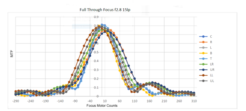
An example of through-focus MTF data that gives an MTF result for each focal setting for each of nine regions across a display. Each line shows the results for a given region, and each dot shows the MTF measurement at a specific focus motor count. The most uniform focus across all regions in the display is found at around 10 focus motor counts of the measurement system.
There is no effective way to test for through-focus MTF using a manual lens. There are too many focal distances to test, the optimal focus of each measurement region is unknown, and each manual adjustment of the lens can significantly increase measurement time and risk of error. This is especially true if the entrance pupil position is changed with each focal adjustment (as with extension-focus lenses).
What XR device makers need to ensure visual quality is a single display measurement solution to accommodate multiple focal points, quickly and easily.
The XRE Lens: A Flexible Solution
Radiant’s new XRE Lens addresses these testing needs with a patent-pending design that incorporates a unique internal-focus mechanism. The system provides electronic focus that can instantly adjust to multiple focal planes. Used with a ProMetric camera and the TT-ARVR™ module of our TrueTest™ software, the XRE Lens can be used to measure XR displays at a range of focal distances (from 0.5 m to infinity) with ultimate precision.
Since the XRE Lens’s focus mechanism is internal, refocusing does not increase the overall length of the system or change the position of the aperture prior to capturing a new measurement. It eliminates the need for manual refocusing and reduces potential alignment and focus errors. And, the lens system can function hands-free during focus adjustment, meaning electronic focus can be automated in sync with measurement sequences for maximum efficiency.
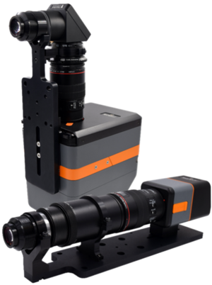
Radiant’s XRE Lens solution, in folded configuration paired with a ProMetric I Imaging Colorimeter (back) and non-folded with a ProMetric Y Imaging Photometer (front).
To learn more about visualization parameters, quality considerations, and measurement solutions for XR devices—those with liquid lenses or a wide variety of other optical designs—watch the webinar “Replicating Human Vision for XR Display Testing: A Flexible Optical Solution for In-Headset Measurement” presented by Radiant’s Optical Development Manager.
CITATIONS
- “Lenses go liquid.” European Inventor Award, 2013. (Retrieved May 27, 2022)
- Liquid Lens Basics, Section 7.1 of the Imaging Resource Guide, Edmund Optics. (Retrieved 5/26/22)
- “Lenses go liquid.” European Inventor Award, 2013. (Retrieved May 27, 2022)
- Bruno Berge, Jérôme Broutin, et al., “Liquid Lens base on electrowetting: actual developments on larger aperture and multiple electrodes design for image stabilization or beam steering.” SPIE Proceedings Volume 8616, MOEMS and Miniaturized Systems XII; 861612, 2023. DOI 10.1117/12.2006847
- Liquid Lens Features, Applications, and Technology, Section 7.2 of the Imaging Resource Guide, Edmund Optics. (Retrieved 5/26/22)
- Ibid.
- Ibid.
- Leihao Chen, Michele Ghilardi, James J.C. Busfield, and Federico Carpi, “Electrically Tunable Lenses: A Review.” Frontiers in Robotics and AI, 8:678046, June 9, 2019. DOI 10.3389/frobt.2021.678046
Join Mailing List
Stay up to date on our latest products, blog content, and events.
Join our Mailing List
