A More Accurate Measure of MTF to Ensure Quality of AR/VR/MR Devices
Ensuring the visual quality and accuracy of augmented-, virtual-, and mixed-reality (AR/VR/MR) display devices requires precise measurement and qualification. Because these head-mounted displays (HMDs) fill a significant portion of the user’s field of view (FOV)—typically 10-50° for AR and 100-120° for VR—even minor defects and irregularities can be observed by a device wearer, potentially interfering with functionality and user experience.
The available equipment on the market for testing AR/VR/MR displays may all be similar in some respects. However, there are optical differences between how AR/MR devices are configured vs. VR devices. To obtain the most accurate measurement of AR/MR displays often requires precise test equipment capabilities and a unique testing set up to ensure that measurement and qualification of a device will replicate the human visual experience.
There are many different characteristics of measurement systems that can significantly affect their performance and accuracy. For example, form factor and FOV are key considerations, and issues such as distortion, ghosting, and stray light can all affect testing accuracy. One particularly significant characteristic of any AR/VR measurement system is its optical modulation transfer function (MTF) performance.
Many AR/VR/MR device measurement solutions on the market include a camera and specialized lens with a form factor designed to work within a headset to mimic where the user’s eye would be. Specifications of the camera or imaging system and the lens, however, can affect the accuracy of measurements taken by the various systems.
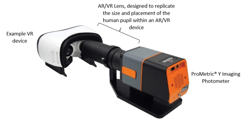
An example of current AR/VR/MR metrology solutions, Radiant’s ProMetric® Imaging Photometers and Colorimeters and our AR/VR Lens are carefully designed and calibrated for accuracy and repeatability.
Understanding Measurement System MTF
Every lens can be characterized by its MTF, which “is a measure of the ability of an optical system to transfer various levels of detail from object to image. Performance is measured in terms of contrast (degrees of gray), or of modulation, produced for a perfect source of that detail level.”1 MTF incorporates the resolution and contrast capabilities of a lens or imaging system into a single specification.
Optical designers often use MTF to compare the performance of optical systems. In fact, “MTF is one of the best tools available to quantify the overall imaging performance of a system in terms of resolution and contrast.”2
For example, a display metrology system with a low overall MTF may not provide reliable data for device testing because measurement results may be affected by system MTF. Poor system MTF can make it difficult to determine if device under test (DUT) performance characteristics that are identified in testing are from the device alone or are being introduced by lens/system MTF.
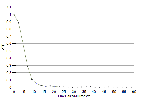
One way to determine system MTF is with a Line Pairs test: a test image is presented with lines spaced at a certain number of line pairs per degree. To ensure the most accurate measurements by our AR/VR Lens, Radiant Vision Systems obtains MTF data for its lens, measuring the percentage of transferred contrast vs. the frequency (cycles/mm) of line pairs. At 30 cycles/mm at 0° (Center MTF), our ARVR Lens exhibits an MTF that is greater than 0.6, indicating high-quality imaging capability.
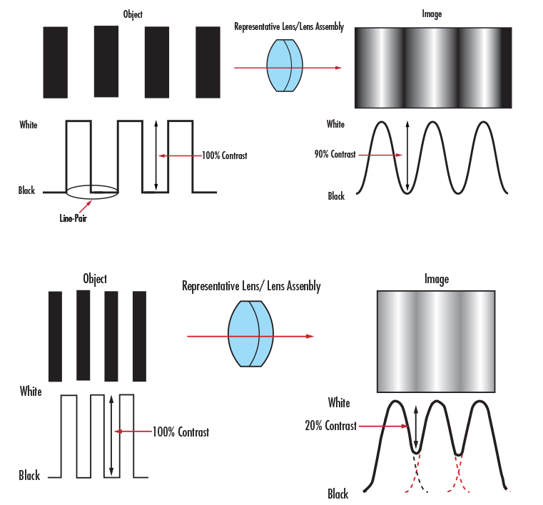
Line Pair contrast test example (top) shows excellent MTF performance reproducing 90% image contrast, compared to poor lens MTF performance of only 20% contrast reproduced in the bottom image. (Image Source: Edmund Optics)
Contrast Sharpness
The sharpness (clarity) of projected AR/VR/MR images depends in part on how well a display can represent contrast—the demarcation between different image elements. MTF is the primary method used to measure the spatial contrast of displays to assess the intersection of bright and dark image areas. Standard tests for clarity include Slant Edge MTF and MTF using Line Pairs (based on Michelson contrast calculation).
One limitation of Line Pairs testing is that it can only characterize the MTF of one position of the measurement system per test instance. The Slant Edge MTF test can be a more efficient way to determine performance of an imaging system. To determine MTF, the system takes a series of cross-sections through the display area, as shown in the images below, then the derivative of those data are represented as a line spread function, to which we apply a Fourier transform to yield the MTF plot.
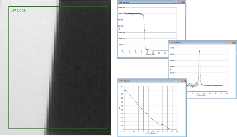
Slant Edge test measures MTF performance as the ratio between black and white areas on a contrasting slant pattern, per ISO 12233.
One challenge of any modern AR/VR/MR display testing approach is that, essentially, imaging systems are measuring a pixilated display with a pixilated sensor, making it necessary to remove any artifacts caused by having the DUT perfectly aligned with the sensor pixels—measuring a slanted edge obliviates this issue, as specified in ISO Standard 12233. For a single display, MTF can be measured to a defined threshold that is acceptable for display performance. MTF measurements can also be used to accurately compare device to device.
Modulation transfer function (MTF) is calculated in Radiant Vision Systems TT-ARVR™ Software using a Slant Edge MTF analysis to determine overall image clarity.
Line Spread Function Method Yields Improved Accuracy for AR/MR MTF Measurement
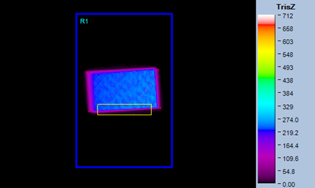
In theory, MTF Line Pair and Slant Edge tests work quite well to characterize the MTF of the imaging system itself. But when trying to measure a pixelated display with this methodology, certain problems can interfere with getting accurate results. First, if the imaging system has a high-enough resolution then it can actually resolve the display pixels themselves, meaning that the system is seeing contrast between the pixel separation, not contrast of the displayed image.
For example, in the images below, we want to measure the contrast between the dark and light regions (left image, shown in false color), but the system is only capturing the pixilation noise of the display (left graph). The second graph (right graph) represents this data as a Line Spread Function (LSF) of the Slant Edge. After Fourier transform, the LSF graph is showing a large spike that is not due to any real, physical phenomenon of the display but is simply a result of the pixilation noise in that region.

To address this pixilation issue, Radiant has pioneered a new test for MTF, which we call the Line Spread method.3 Instead of displaying a box and measuring the contrast of the edge, we display a discreet line of pixels. We are directly measuring the line spread. By characterizing the transition of the line, we can measure LSF directly and correctly characterize it, yielding a more accurate result.
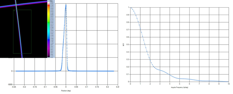
Line Spread Function test (far left image) provides direct measurement of contrast (left graph), which is then transformed into an accurate characterization of the display’s MTF performance.
Accurate measurement of AR/VR/MR/XR devices requires specialized equipment and approaches. The LSF test method is just one example of Radiant's continuing hardware and software development to provide device makers with innovative display metrology solutions to ensure the quality of HMDs and the user experience.
Eric Eisenberg is Optics Development Manager for Radiant.
CITATIONS
- “Modulation Transfer Function”, Optikos Corporation. (Retrieved June 7, 2021)
- “Introduction to Modulation Transfer Function”, Edmund Optics. (Retrieved June 7, 2021)
- Eisenberg, E., Jensen, J., "Measuring and qualifying optical performance of AR/VR/MR device displays and addressing the unique visual requirements of transparent AR/MR displays." SPIE AR|VR|MR Conference presentation, February 2, 2020.
Join Mailing List
Stay up to date on our latest products, blog content, and events.
Join our Mailing List
