The World's Most Advanced HMD
The F-35 Gen III Helmet is the most advanced helmet-mounted display (HMD) in the world. It was created by Rockwell Collins, in concert with Lockheed Martin, the prime contractor responsible for making the F-35 Lightning II Joint Strike Fighter plane that pairs with this advanced helmet.
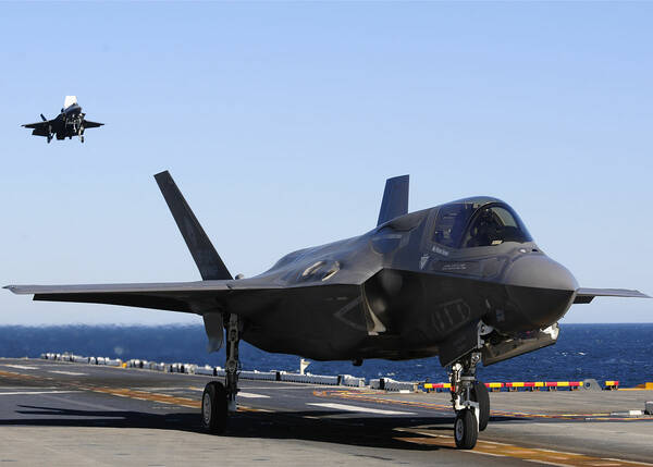
F-35 Lightning II fighter planes.
At the recent Surface Mount Technology Association (SMTA) International Conference, I had a chance to see the Keynote presentation by Ron Heberlein, Pr. Program Manager at Rockwell Collins, and Scott “Shark” McLaren, the F-35 experimental test pilot at Lockheed Martin who was the first to try out the helmet during development.
Development of HMD Technology
In aviation, “situational awareness” is key. A pilot has to continuously monitor and assess multiple informational cues—visual, instrumentation readings, sounds—to fly the aircraft, navigate, and respond to flight conditions with precision and safety. For military pilots, mission-related tactical information must also be factored in. Split-second decision making can mean life or death.
Head-up displays (HUDs) consolidate information on a compact screen that allows pilots to quickly grasp the data they need without looking down at an instrument panel (looking away from the exterior environment). The first operational military HUD was used in 1961 to provide pilots with critical aircraft and targeting information. The earliest HMD systems used Cathode Ray Tube (CRT) screen technology; CRT screens are still in use in some aircraft today, due to their relatively low cost and longevity. However, some of the latest HMD screens use Organic Light Emitting Diode (OLED) display technology.
With the advent of guided missile technology, fighter pilots need to be able to “see” targets that aren’t right in front of them. The first operational HMDs came out in the 1970s to aid in targeting heat-seeking missiles. In the 2000s, engineers integrated HUD technology into HMDs, with co-development since then.
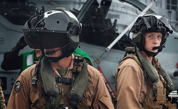
U.S. Marine Corps “Super Viper” helicopter pilots, wearing 2010-era helmets with integrated HUD displays.
Modern Helmet Design
Key components of an advanced helmet-mounted display system (HMDS) includes the helmet itself (protecting the pilot’s head), an active noise reduction headset, a night vision camera, the display visor, a display unit plus electronics assembly that projects images and symbology onto the display visor, and a display management computer (DMC). A military pilot helmet presents a unique set of functional and design requirements:
- It must withstand air maneuvers that create forces up to 9G
- The display visor has to be absolutely clear (see-through) but also coated so that projections will reflect off the inner surface of the screen to be readable to the pilot.
- Display performance requirements include:
- Binocular, high-brightness, wide field of view (FOV) display
- High accuracy in all directions
- Low latency
- 360° night-vision capability
- And not least of all, it must provide comfort and safety for the pilot, meaning:
- Light weight to minimize fatigue
- Protection in the event of an ejection at 550 knots (about 633 mph)
- Ballistics protection
F-35 Generation III Helmet
To create the state-of-the-art F-35 helmet, Rockwell’s designers had to tackle a number of challenges. First, they needed to fit the equivalent of two 30-pound HUDs onto a helmet where the total system weight needed to be less than 5 pounds. To do this, optics and electronics were miniaturized, and the designers made extensive use of newer plastics and composite materials that offer high strength and durability at minimal thickness and weight.
General (non-helmet-mounted) aircraft HUD systems today offer excellent accuracy; the F-35 designers needed to replicate their capability within the restricted display area of a helmet and visor. To do this, they developed a complex, multi-sensor head tracking system, used cutting-edge optics, and set manufacturing tolerances at significantly smaller than the width of a strand of hair.
Because ejection safety is also a key performance requirement, the F-35 design team had to meet all of the helmet performance and weight requirements without compromising the protection needed for a 550-knot ejection. Mr. Heberlein disclosed that, in addition to using state-of-the-art materials, the “secret” to solving this challenge was simply to do a whole lot of testing, ejecting manequins over and over again at high speeds!
To support the design and manufacturing of the helmet and all its component parts, Rockwell Collins tapped into a global network of specialty suppliers, and used complex testing equipment to verify quality and performance.
The HMD is not a stand-alone device, but is just one part of the complex F-35 fighter jet systems. The HMD is integrated with a helmet tracker/transmitter unit (HTU), which tracks the pilot’s head movements to ensure that the camera images and other data displayed reflect the pilot’s line-of-sight (LOS) second by second. Some of the images are created using a fixed camera assembly (FCAM) unit. The display management computer (DCM) controls all helmet elements and is interfaced to multiple aircraft systems.
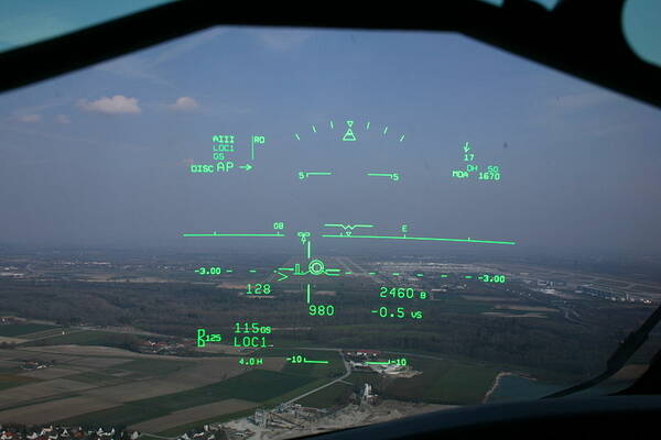
Example of basic aviation symbology on a HUD display.
Custom Fitting
In the fabrication process, each helmet must be custom fit for the pilot who is going to wear it. The baseline design of the helmet must work for any pilot from the 5th to the 95th percentile for head geometry. This necessitates multiple helmet sizes, and the display unit must be adjustable to fit multiple optical mounting locations to align with the pilot’s eyes.
The custom-fitting itself is a two-day process involving a series of measurements and adjustments, including taking a laser scan of the pilot’s head to establish pupil location and determine helmet size. Custom pads are then milled to go inside the helmet to ensure a close fit to the pilot’s skull. The display unit placement is adjusted to match the pilot’s pupil location, and the visors are trimmed.
Finally, all the individual components are assembled, and the HMD is subjected to functional tests to further refine alignment of the display to the pilot’s eyes. For example, key symbology must be projected on the display at an optimal location in relation to the pilot’s LOS. The F-35 HMD’s visor-projected display has the following capabilities:
- 30° ´ 40° wide FOV with 100% overlap
- Under night-time conditions, images are projected directly by the HMD eliminating the need for separate night-vision goggles
- Aircraft and mission-based symbology is combined
- LOS tracking, which enables the pilot to target weapons by looking at and designating targets
The helmet tracker system corresponds to the pilot’s LOS, using magnetic tracking and inertial tracking with complex inputs and outputs based on auto-harmonization and auto-alignment algorithms. Finally, the helmet system includes recording capability for video debriefing.
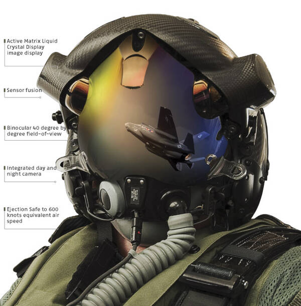
Illustration of the F-35 Lightning II HMD during the development phase in 2010 (The recent SMTA presentation stated the F-35 Generation III helmet has a 550-knot ejection safety requirement, not 600 knots as shown in the image).
A Pilot’s View
Once a pilot puts on the helmet and straps into the cockpit of an F-35 fighter, all of the careful planning, testing, development, and refinement come together. From the pilot’s vantage point, the world becomes oriented around the center point of his view, straight down the nose of the aircraft. This is referred to as the “visual hub.” When the pilot turns his head to either side, this is called an “off-axis” view.
The plane’s camera system presents a range of visual input in the helmet display beyond what’s in the field of view outside the cockpit windows. For example, live video feed from cameras placed at the sides and underneath the aircraft capture a full 360° view, enabling the pilot to see in real-time what’s below and surrounding the jet.
At the same time, infrared (IR) cameras capture supplemental external images for night vision and other low visibility situations. All this visual data can be displayed on the visor’s display screen alongside the standard symbology for the pilot’s immediate reference.
The issue of latency—a slight delay in the display image’s response to a pilot’s head motion—can cause motion sickness and impede the pilot’s situational awareness, so ensuring low latency in the helmet display is critical. However, Mr. McLaren (who is a former Major in the U.S. Air Force) pointed out that latency is not an issue when flying at night, because the pilot is relying on the HMD’s night-vision displays almost entirely, with few or no exterior visual reference points to compete with the displayed image.
The design and display of the symbology is also of key concern to the pilot, who must see and quickly interpret both the normal aircraft symbology and additional mission symbology such as the coordinates of a strike target. McLaren praised the F-35’s mission symbology for supporting the pilot’s overall situational awareness. For example, a triangle symbol signifies a target, and a red triangle signifies another aircraft. These symbols stand out clearly for instant recognition during a mission.
This video shows a simulation of the aircraft and HMD, integrating the images and symbology of night vision cameras, sensors, and tactical mission data.
In the above video, notice at 2:30 how the display "fills in" the parts of the image that would otherwise be blocked from the view by the airplane's windscreen frame as the pilot turns his head to the right. This is an example of the HMD integrating multiple sources of image information in real-time to provide a continuous 360° visual feed. It's a simulation, but if you want to see the F-35C Fighter Jet (“C” for Carrier) and the F-35 HMD in live action deployed on the USS Nimitz, check out the theatrical film, Aircraft Carrier: Guardian of the Seas.
Now playing at an IMAX theater near you.
Ensuring HMD Quality and Performance
The function and performance of the F-35 HMD is in part dependent on the visor’s display screen itself. If information is not displayed clearly, under all ambient lighting situations and operating conditions, then it won’t help—and can even endanger—the pilot and the mission. Ensuring that HUD/HMD display screens are free of defects and function optimally requires careful testing during the production phase. Radiant provides special test systems to evaluate the quality of near-eye displays (NEDS) such as HUDs, HMDs, and AR/VR devices that are viewed close to the human eye.
To learn more about Radiant’s HUD measurement solution, with relevance to both automotive and aerospace display applications, read the whitepaper, “Automated Solutions for SAE standard HUD Measurement”.
To learn more about Radiant’s NED display testing, including our AR/VR measurement solution, watch a recent webinar, “Replicating Human Vision for Accurate Testing of AR/VR Displays”.
Join Mailing List
Stay up to date on our latest products, blog content, and events.
Join our Mailing List
