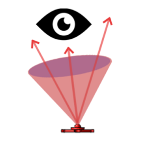
Radiant's near-infrared (NIR) measurement solutions help ensure the accuracy of NIR emitters used for facial & gesture recognition and other 3D sensing applications. NIR light covers wavelengths of the electromagnetic spectrum from approximately 750 to 2500 nanometers (nm), which is beyond human visual perception. NIR-based sensing provides machines with information about objects in the physical environment. When NIR light is emitted and reflected off of an object, an NIR sensor receives the reflected light or light pattern to gauge the distance, size, location, and identifying features of objects in the three-dimensional world.
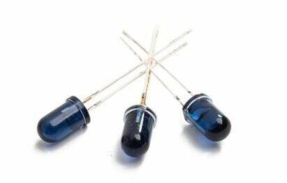
NIR light is ideal for 3D sensing applications because it is invisible to the human eye, making it unnoticeable when cast into a user’s face, eyes, or environment. Proper filtering can remove the visible light spectrum for NIR sensing devices, increasing reliability for sensing in ambient light conditions or poor visibility conditions like rain or fog. However, because the human eye does not respond to NIR light, it is important to measure the emissions from NIR LEDs and lasers that will be used for 3D sensing of humans and their environments.
Radiant's NIR Intensity Lens solution combines a high-resolution imaging radiometer, optical component, and software test libraries for common analyses. Software tests in Radiant’s TT-NIRI™ software include pass/fail parameters and custom output and can be run in sequence to efficiently characterize and qualify light sources used for facial & gesture recognition, eye tracking, and other NIR-based 3D sensing applications. Part of our TrueTest™ software pltaform, it includes specific tests for NIR LEDs, lasers, and structured light patterns.
Explore Solutions:
The NIR range covers approximately 750 to 2500 nanometers of the electromagnetic spectrum, which is outside of the visible light spectrum for human vision.
NIR Applications by Wavelength
| - 780 nm | Eye Tracking |
| - 850 nm | Night Vision, Security Cameras |
| - 905 nm | Short-range Automotive Lidar (ADAS, Autonomous Vehicles) |
| - 940 nm | Facial, Gesture Recognition |
| - 1040-1060 nm | Terrestrial Mapping, Lidar Systems |
| - 1550 nm | Long-range Automotive Lidar (ADAS, Autonomous Vehicles) |
Polar plot and cross section showing radiant intensity (as a function of angle) of an NIR LED, captured by the Radiant NIR Intensity Lens and analyzed in TT-NIRI Software.
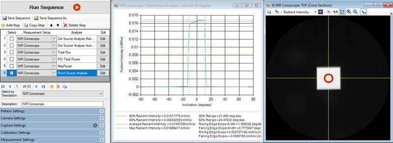
Flood Source Analysis measurement for an NIR source shown in Radiant’s TT-NIRI Software module. Here, light is pulsed through a square diffuser to create a distribution with uniform intensity. The cross-section graph shows peaks of intensity and fall-off at the edges of the source’s emission pattern.
Structured Light Dot Pattern Analysis
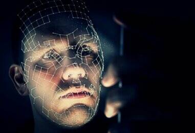
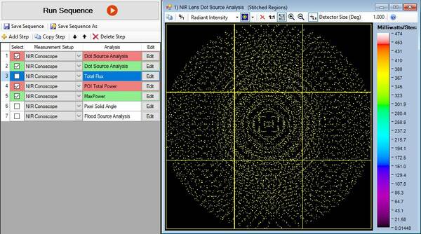
To produce a structured light pattern, a single NIR laser emission is projected through an optical component called a diffractive optical element, or DOE. A DOE splits the laser into multiple emission points, which cast an array of tiny invisible dots in a grid onto a 3D object, such as a person’s face. When the light from each dot is reflected back from the object surface and received by the NIR sensor, the device calculates deformations in the pattern to determine the contours of the object. Effectively, the NIR structured light grid creates a “map” of an object’s 3D features. Structured light sensing is a common method used in biometric security such as facial recognition devices for smart phones and other protected devices or media.
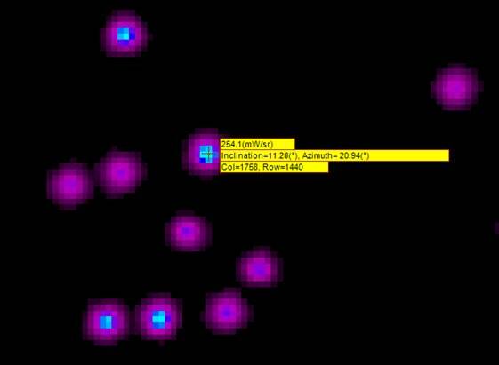
The TT-NIRI Software module automatically identifies and counts each dot in a structured light pattern as a point of interest, outputting data on each dot such as inclination, azimuth, and radiant intensity (W/sr).
The TT-NIRI Software module automatically identifies and counts each dot in a structured light pattern as a point of interest, outputting data on each dot such as inclination, azimuth, and radiant intensity (W/sr).
Measuring patterns produced by DOE ensures accurate and safe sensing of a 3D object’s unique identifiable features. Each dot in a pattern must be accurately positioned and emitted with the intended radiant intensity to ensure it is properly reflected to a device’s NIR sensor and interpreted correctly to identify the individual.
Regardless of the structured light pattern or dot position, shape, or size, Radiant’s radiometric measurement solution automatically identifies points of interest for each dot and outputs data for each dot’s angle of location (azimuth, inclination), maximum intensity, uniformity, and flux. Full dot source analytics are reported in TT-NIRI Software, including maximum peak (strongest emitter) location at x,y, maximum peak inclination/azimuth, maximum peak average, maximum peak solid angle, number of pixels at maximum peak point, spot power uniformity (between dots), total flux, and DOE flux (subtracting the background peak).


